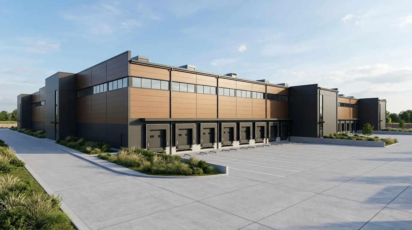
Executive Key Takeaways
- Design from the inside out: freeze machine layouts, crane hooks, and material flow topologies before defining building envelopes or civil footprints.
- Optimize structural column grids to 24m to 30m clear spans to eliminate machine layout constraints while minimizing pre-engineered building (PEB) steel tonnage.
- Establish vertical clear heights based on the highest lifted load plus hook, sling, and roof truss clearances, rather than arbitrary architectural ceiling heights.
- Specify floor slab carrying capacities from localized machine point loads and dynamic vibration footprints, utilizing laser-screeded FM2 finishes.
- Co-locate high-demand MEP utilities along centralized modular distribution corridors to avoid clashes with overhead crane travel envelopes.
- Comply strictly with the National Building Code of India (NBC 2016 Part 4) and Directorate of Industrial Safety & Health (DISH) setback and ventilation mandates.
In commercial and residential architecture, design often begins with an expressive facade or artistic spatial massing. In industrial building design, taking this outside-in approach is a catastrophic capital mistake. A factory is not merely a shelter for equipment—it is an active, precision production tool whose geometry directly governs operating efficiency, material handling costs, and worker safety.
When factory owners commission an architect before finalizing process flows, equipment weights, and crane duty cycles, the resulting facility is plagued by permanent bottlenecks: columns planted directly in the path of CNC machining cells, inadequate clear heights for overhead cranes, cracked floors under heavy point loads, and expensive structural retrofits.
Before the very first architectural line or 3D elevation is drafted, manufacturing promoters and facility directors must lock down seven foundational engineering parameters. This guide outlines the essential pre-design decisions required to deliver an efficient, cost-optimized, and audit-ready industrial manufacturing building.
Inside-Out Design: Process Kinematics Precede Architecture
The golden rule of industrial architecture is that process flow dictates building form, never the reverse. An industrial building must be wrapped snugly around an optimized production process like a protective tailored suit.
The design process begins by developing an unconstrained machine layout—mapping raw material intake, primary machining, secondary finishing, quality metrology, and finished goods marshalling. Whether the flow follows a linear I-shaped spine or an integrated U-shape, material travel distances must be minimized and unidirectional flow preserved without backtracking.
Only once equipment coordinates, material handling paths, and maintenance zones are frozen should civil columns and perimeter walls be introduced.
Column Grid Spans & Structural PEB Economics
The spacing between structural columns determines the flexibility of the shopfloor for decades to come. An overly dense column grid (e.g., 6m × 6m or 8m × 8m) significantly limits machine placement, prevents reconfiguring machining cells, and creates frequent collision risks for forklifts.
Conversely, infinite clear spans across an entire 60-meter facility create massive structural steel bending moments, dramatically inflating pre-engineered building (PEB) fabrication and foundation costs. The engineering sweet spot for modern industrial manufacturing balances bay span with steel weight:
| Column Grid Span | Structural System | Application & Cost Evaluation |
|---|---|---|
| 12m to 18m Clear Span | Standard PEB Portal Frame | Economical steel weight (28-35 kg/sqm). Ideal for raw material stores, assembly bays, and low-crane ancillary workshops. |
| 24m to 30m Clear Span | High-Span PEB Frame with Tapered Rafters | Optimal balance for heavy manufacturing (35-48 kg/sqm). Accommodates dual CNC machine lines, central gangways, and 10-30 MT EOT cranes. |
| 36m+ Column-Free Bay | Jack Beams or Heavy Structural Trusses | Higher steel weight (55-75+ kg/sqm). Justified only where large monolithic aerospace, heavy fabrication, or multi-axis gantry machines require unobstructed floor space. |
Vertical Clear Height & Crane Runway Integration
Determining clear internal height is one of the most critical irreversible decisions in factory design. Setting the eave height too low restricts future crane additions, reduces natural ventilation, and traps heat. Setting it excessively high increases HVAC conditioning volumes and structural wind load resisting requirements.
Clear height must be calculated systematically using a bottom-up vertical stack analysis:
- Floor to Machine Bed: Height of the tallest machine or fixture (e.g., 2.5m to 4.0m for vertical machining centers).
- Maximum Component Lift Height: Elevation required to lift the heaviest workpiece or tooling above adjacent machines with a 500 mm safety buffer.
- Rigging & Sling Geometry: Vertical dimension of lifting chains, spreader beams, and crane hook blocks (typically 1.5m to 2.5m).
- Crane Rail Elevation: Minimum height of the crane rail above the finished floor, ensuring crane end-carriages clear structural roof haunches by at least 300 mm.
- MEP Service Envelope: Clearance reserved above the crane bridge girder for high-bay lighting, fire sprinkler pipes, and ventilation ductwork without risk of mechanical impact.
Industrial Floor Slab Engineering & Heavy Payloads
The floor slab is the unsung workhorse of any industrial building. Unlike commercial flooring, an industrial slab must withstand intense dynamic vibration from reciprocating machinery, heavy concentrated wheel loads from reach trucks, and high point loads from pallet racking legs.
A comprehensive floor specification must integrate geotechnical subgrade compaction, slab thickness (typically 150mm to 250mm M30/M35 grade concrete), steel rebar reinforcement or poly/steel fiber reinforcement, and armored leave-in-place contraction joints. Surface finishes must meet TR34 FM2 flatness criteria to prevent mast oscillation and wear on high-lift equipment.
MEP Utility Arteries & Crane Envelope Coordination
Piping, high-voltage busducts, and compressed air lines must never be routed opportunistically across an industrial building. Utility distribution must be designed along dedicated, coordinated structural arteries.
Utility headers should be consolidated onto structural pipe racks mounted along perimeter PEB columns, maintaining strict vertical segregation: electrical busducts and data cable trays on the top tier, compressed air and inert gases in the middle, and cooling water and effluent pipes on the bottom tier. This eliminates the risk of water leaks dripping onto live electrical switchgear and keeps utility lines outside the travel envelope of crane hooks.
NBC 2016 & DISH Statutory Building Bylaws
Building designs must strictly adhere to the National Building Code of India (NBC 2016) and state Directorate of Industrial Safety & Health (DISH) / Factory Inspectorate mandates. Overlooking statutory spatial rules during early planning can delay building occupancy permits by months or require costly civil demolition.
Key compliance requirements include maintaining a minimum 6.0-meter clear, unobstructed asphalt fire tender driveway around the entire building perimeter, providing dual independent fire exits within maximum travel distance limits (30 meters for industrial occupancies), and ensuring minimum natural ventilation window areas equal to at least 10% of total floor area.
Natural Daylighting, Ventilation & Thermal Envelope
Energy efficiency and worker productivity depend heavily on thermal building envelope performance. Uninsulated metal roofs turn factories into thermal ovens during peak summer months, increasing machine hydraulic temperatures and operator fatigue.
Best practices for sustainable industrial building envelopes include specifying double-skin standing seam metal roofs with 50mm high-density mineral wool or PIR insulation, incorporating polycarbonate skylights covering 4% to 6% of the roof area to achieve 300+ Lux daytime illumination without electric lighting, and installing continuous aerodynamic roof ridge ventilators to expel warm air naturally.
Built-In Expansion Vectors for Phase 2 Growth
A well-designed factory accommodates future business growth without interrupting active production. The building must incorporate pre-engineered expansion vectors from day one.
Gable end portal frames should be detailed with demountable bolted sheeting rails rather than permanent masonry walls. Main utility headers (compressed air, cooling loops, and HT busducts) must terminate in valved and blinded flange connections at the building boundary, allowing Phase 2 expansion to connect seamlessly in a single weekend turnaround.
Critical Mistakes to Avoid in Facility Planning
1. Freezing civil drawings before equipment data is verified
Leads to undersized machine pits, structural column clashes with crane travel, and major civil rework costs.
2. Compromising on perimeter fire access driveways
Violates NBC 2016 Part 4 fire codes, resulting in rejection of statutory Fire NOCs and building completion certificates.
3. Specifying uninsulated single-skin metal roofing
Causes indoor temperatures to reach 45°C in summer, accelerating electronic drive failures and severely reducing worker productivity.
4. Omitting dynamic crane load impact factors during PEB sizing
Neglecting horizontal crane surge forces leads to structural frame sway, crane runway rail misalignment, and accelerated wheel wear.
5. Failing to plan utility distribution corridors in 3D BIM
Results in costly site collisions between process piping, HVAC ductwork, structural knee braces, and crane gantries.
Engineer Your Industrial Building as an Instrument of Manufacturing Excellence
Industrial building design is an engineering discipline where process efficiency, structural rigor, and statutory compliance converge into a high-performance production envelope.
At Vishwakalpa Design Planning and Management, we guide manufacturers through every stage of facility planning—from initial process zoning and column grid optimization to turnkey PMC site delivery.
Frequently Asked Questions
What is the most economical column grid span for a manufacturing building?
A column span of 24 to 30 meters generally provides the best economic balance in PEB manufacturing facilities, offering wide unobstructed aisles for machine layouts while keeping structural steel tonnage optimized between 35 and 48 kg/sqm.
How do you determine the required clear height for an industrial factory?
Clear height is determined by adding the height of the tallest machine, the maximum lift height of workpieces, crane hook and sling geometry, crane runway girder depth, and safety clearance to the lowest structural roof truss haunch.
Why is TR34 FM2 floor flatness critical in industrial buildings?
FM2 flatness tolerances prevent mast vibration and tilt on high-reach forklifts and heavy material handling equipment, eliminating floor cracking and ensuring precision equipment operates without foundation settlement.
How does Vishwakalpa support factory owners with industrial building design?
Vishwakalpa provides end-to-end industrial architecture, PEB structural engineering, MEP coordination, 3D BIM clash detection, and statutory approval guidance for manufacturing facilities across India.

Explore More Technical Guides
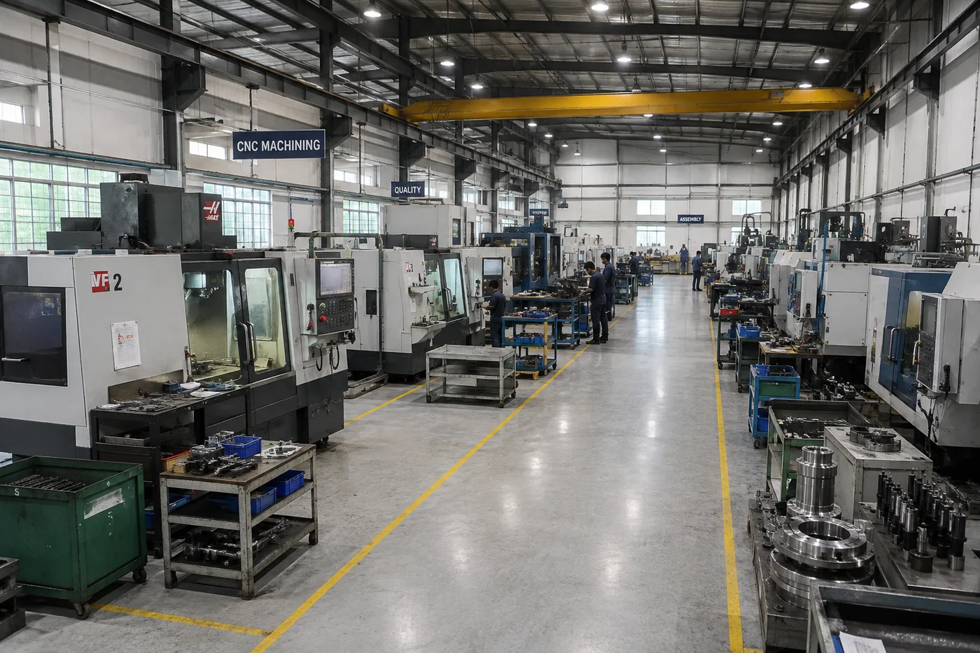
Precision Machining Unit Design Guide
12 min read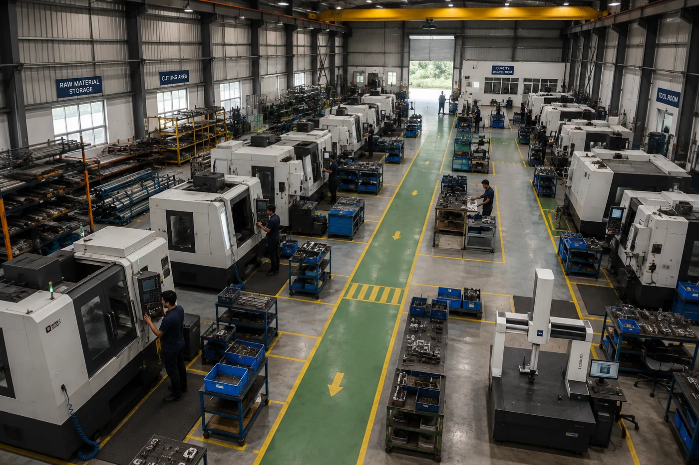
CNC Machining Plant Layout Planning Guide
14 min read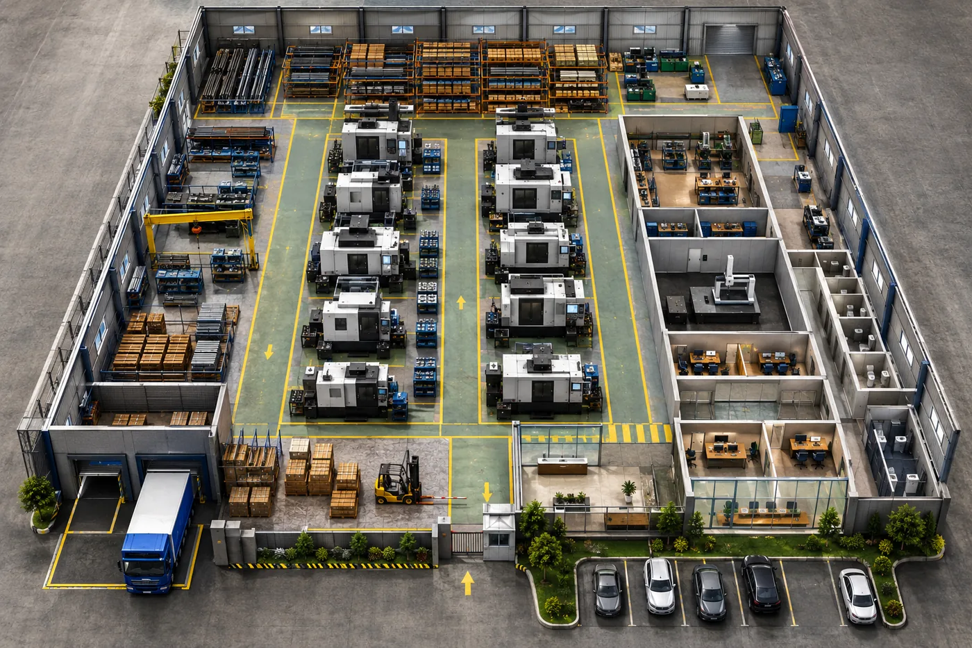
CNC Plant Space Requirement Calculation Guide
15 min read
What Is Industrial Architecture?
10 min read
Foundry Layout Planning Guide
14 min read
Plant Expansion Readiness Guide
11 min read
Plastic Recycling Plant Design Guide
12 min read
Factory Master Planning Decisions
13 min read
Plant Material Flow Planning Guide
12 min read
Hiring an Industrial Design Consultant
12 min read
Industrial Warehouse Planning
12 min read
Pharma Facility Planning & GMP
14 min read