Executive Key Takeaways
- Select the right flow topology: Straight Line (I-Flow) for high-volume linear processes, or U-Shape for flexible cellular setups with common shipping/receiving docks.
- Size Work-in-Progress (WIP) staging squares on the floor with yellow thermal lines to prevent informal aisle clutter.
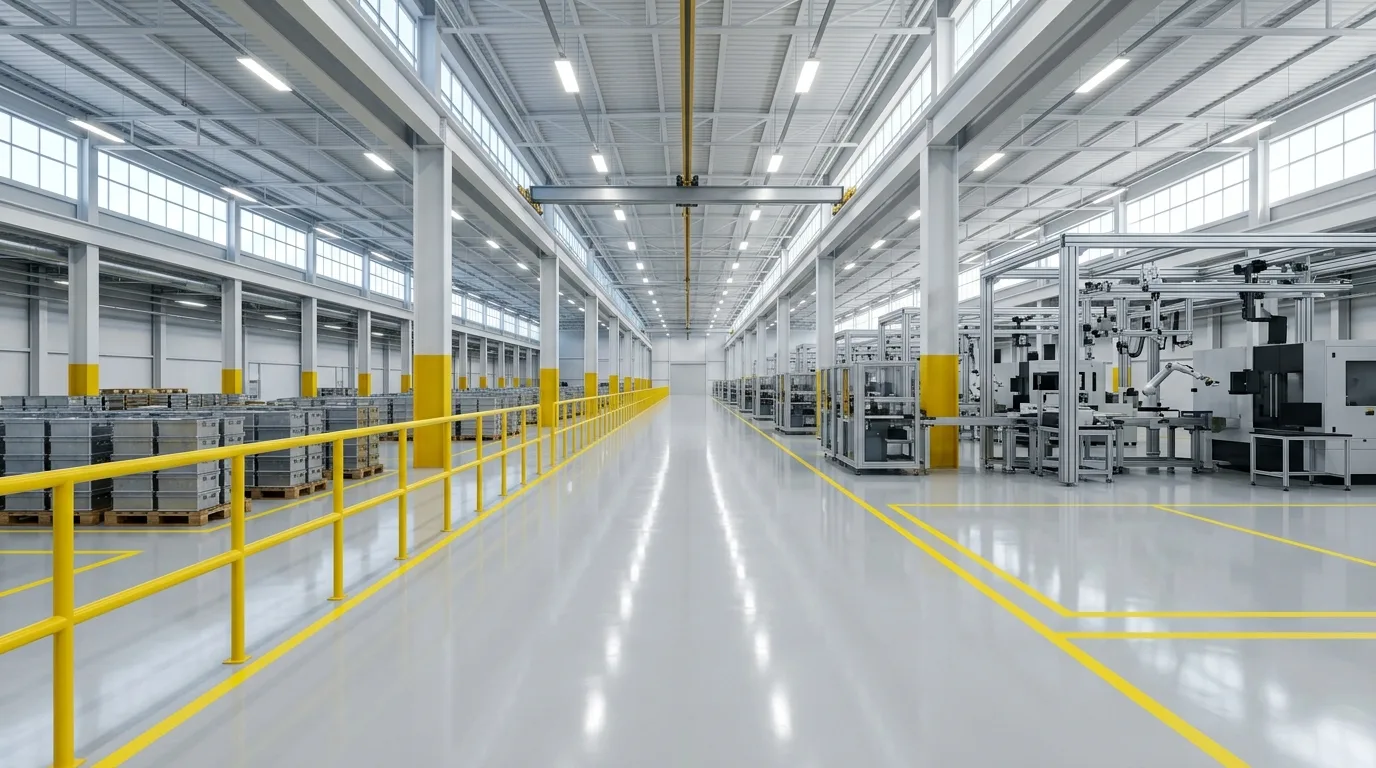
- Physically separate pedestrian walkways from forklift lanes using heavy steel crash barriers (minimum 3.5m to 4.0m two-way forklift aisles).
- Position raw material receiving and finished goods dispatch to minimize total travel distances across heavy handling routes.
- Integrate point-of-use storage and overhead monorails to reduce operator fatigue and material handling touches.
In any manufacturing plant, the cost of moving materials adds zero value to the finished product. Every time a workpiece is picked up, transported across an aisle, set down in an unorganized staging area, and re-handled by a forklift, production costs rise and delivery lead times lengthen.
Effective material flow planning is the science of establishing smooth, progressive movement from raw material intake to final dispatch. A disciplined flow strategy eliminates travel waste, prevents high-speed forklift collisions, keeps Work-in-Progress (WIP) under control, and unlocks significant capacity without adding floor space.
The Physics of Factory Material Flow: Distance vs Handling Waste
Material handling accounts for 20% to 50% of the total operating costs in manufacturing plants, yet represents 0% of the value perceived by the customer. The primary objective of material flow engineering is to minimize the total travel distance of parts (measured in ton-meters) and eliminate redundant touches.
When material backtracking occurs—where a part moves forward to rough machining, backward to heat treatment, and forward again to finishing—it consumes forklift capacity, creates crossing traffic conflicts, and increases WIP queues.
Comparing Core Flow Topologies: Straight Line vs. U-Shape vs. Cellular
The choice of material flow pattern depends on product variety, production volume, and building geometry:
Straight-Line (I-Flow)
Raw material enters at one end, progresses continuously through operations, and exits at the far end. Ideal for long-span PEB sheds, continuous wash lines, and high-volume dedicated lines.
U-Shaped Flow
Receiving and shipping are located on the same building facade, while the process curves in a horseshoe. Maximizes dock leveler flexibility, allows shared logistics personnel, and shortens communication paths.
Cellular Flow
Machines grouped into self-contained operational clusters (e.g. lathe + VMC + deburring + QC). Parts complete all operations inside the cell before moving to the central assembly spine.
Spine / Tree Flow
A central wide arterial logistics corridor with sub-assembly bays branching off perpendicularly. Best suited for complex discrete equipment and automotive assemblies.
Work-in-Progress (WIP) Buffer Sizing & Intermediate Staging
Without dedicated WIP floor squares, batches waiting between operations spill into transport aisles, forcing forklifts to swerve and creating chaotic choke-points. WIP buffers must be treated as engineered stations with designated floor footprints.
Buffer sizing is calculated from line balancing equations: (Buffer Area = Batch Quantity × Unit Footprint × Stacking Factor × 1.3 Circulation Factor). Marking buffer squares with high-visibility epoxy lines and setting strict maximum batch limits enforces visual management and lean flow.
Forklift & Pedestrian Routing Safety: Eliminating Blind Spots
Forklift-pedestrian collisions are the leading cause of fatal industrial workplace accidents in manufacturing facilities. Floor striping alone is insufficient; modern factory layouts enforce physical separation.
Two-way forklift aisles must maintain a minimum clear width of 3.5m to 4.0m to allow counterbalanced trucks to pass safely with loads. Dedicated pedestrian walkways (minimum 1.2m width) must be protected by heavy structural steel crash barriers (rated to withstand 5-ton impacts at 10 km/h). Blind 90-degree aisle corners should be replaced with chamfered column corners and overhead convex mirrors.
Receiving & Dispatch Dock Strategy: Perimeter vs. Cross-Docking
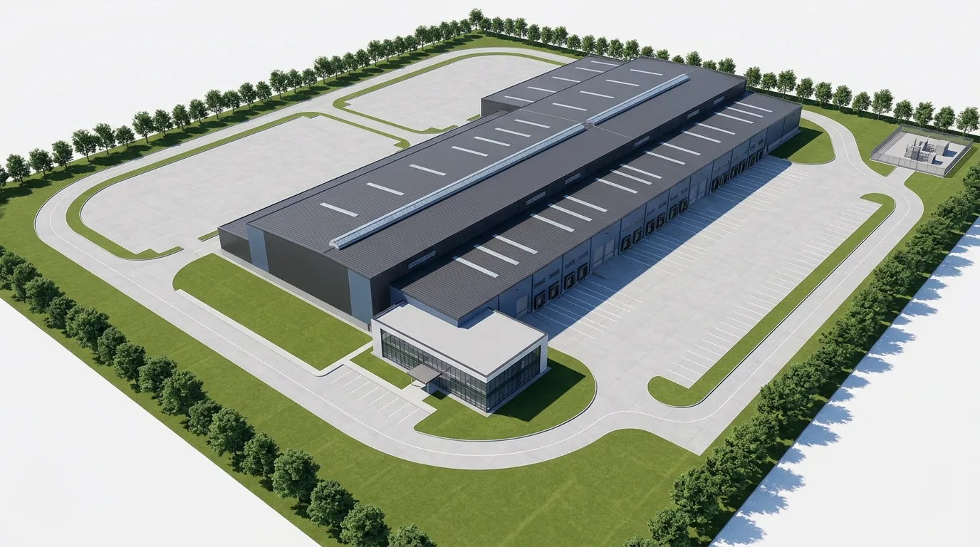
Loading docks are the primary interface between factory logistics and external road transport. Docks should be elevated to match standard truck bed heights (1.2m to 1.3m above apron level) and equipped with electro-hydraulic dock levelers.
Separating inbound raw material staging from outbound finished goods prevents packaging contamination and eliminates staging confusion. For high-throughput FMCG or packaging plants, cross-docking designs allow immediate transfer of incoming components directly to dispatch staging without long-term warehouse storage.
Overhead Handling, Monorails & Automated Material Flow
To clear floor space and reduce forklift congestion, modern industrial facilities leverage vertical cubic volume through overhead material handling systems. Electric Overhead Traveling (EOT) cranes handle heavy dies and raw bar stock along the main crane runway.
For continuous assembly operations, overhead monorail hoists and Automated Guided Vehicles (AGVs) following optical or magnetic floor tracks transfer workpieces between workstations silently, predictably, and with zero forklift interference.
Flow Topology Selection Matrix
Use this engineering selection matrix to determine the optimal material flow topology for your manufacturing unit:
| Flow Topology | Best Suited For | Key Advantages | Key Constraints |
|---|---|---|---|
| Straight Line (I-Flow) | Continuous wash lines, rolling mills, high-volume production | Zero backtracking, simplest linear conveyor progression | Requires long, narrow plot; separate docks at opposite ends |
| U-Shaped Flow | Machining units, automotive components, fabrication | Shared loading docks, flexible staffing, compact envelope | Can create crossing conflicts if intermediate legs cross |
| Cellular Flow | High-mix low-volume parts, CNC turning/milling cells | Minimal WIP buffer, rapid cycle times, high quality ownership | Requires multi-skilled operators and duplicate tooling |
| Spine / Arterial Flow | Complex machinery, heavy assembly, multi-line campuses | Centralized logistics spine, modular bay expansion | High traffic density in the central spine requires wide 6m aisles |
Critical Mistakes to Avoid in Facility Planning
1. Narrow forklift aisles causing machine collision damage
Undersizing aisles below 3.0m forces forklifts to graze machine panels and structural columns.
2. Unplanned WIP staging overflowing into transit aisles
Allows pallets of castings or machined parts to block emergency exit routes and forklift lanes.
3. Backtracking material paths between processing stages
Increases travel distances by 200% to 300% and creates frequent transport aisle congestion.
4. Sharing a single door for loading and unloading
Results in inbound raw materials being erroneously placed into outbound dispatch queues.
5. Inadequate clearance around CNC chip conveyors and bins
Forces operators to maneuver forklifts through tight machine gaps to empty waste scrap.
Design Material Flow Once, Profit from Lean Operations for Decades
Every meter of material transit eliminated permanently reduces operating overhead, cuts forklift fuel and maintenance costs, and speeds order delivery.
At Vishwakalpa Design Planning and Management, we integrate mechanical engineering logic into architectural facility designs, creating lean, safe, and world-class manufacturing campuses.
Frequently Asked Questions
What is the most efficient material flow in a factory?
There is no single universal flow; efficiency depends on product volume and mix. High-volume dedicated lines thrive on Straight-Line (I-Flow), whereas high-mix component manufacturing performs best with U-Shaped or Cellular flows.
How wide should a factory forklift aisle be?
Standard two-way forklift aisles for counterbalanced 2.5-ton to 3.0-ton forklifts require a minimum clear width of 3.5 to 4.0 meters. One-way aisles require at least 2.8 to 3.2 meters plus pallet clearances.
How do you reduce Work-in-Progress (WIP) on the factory floor?
By balancing cycle times between consecutive machine operations, introducing kanban pull signaling, reducing batch transfer sizes, and establishing clearly demarcated, limited-capacity WIP floor squares.
How does Vishwakalpa assist with material flow optimization?
Vishwakalpa prepares detailed material travel distance matrices (ton-meters), evaluates linear vs U-shaped flow options, coordinates PEB structural column spacing, and designs safe forklift and pedestrian routes.

Explore More Technical Guides
Precision Machining Unit Design Guide
12 min read
CNC Machining Plant Layout Planning Guide
14 min read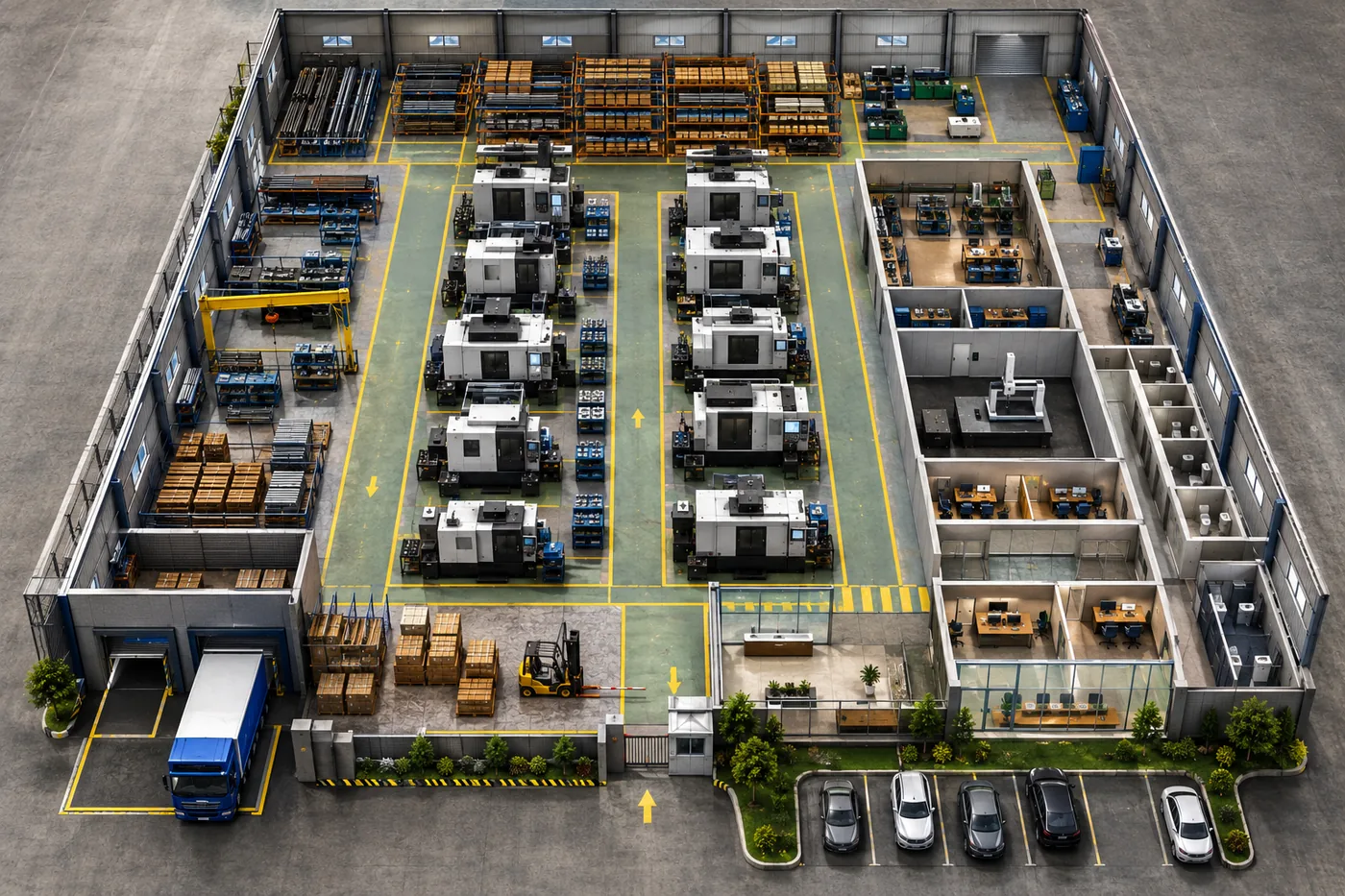
CNC Plant Space Requirement Calculation Guide
15 min read
What Is Industrial Architecture?
10 min read
Foundry Layout Planning Guide
14 min read
Plant Expansion Readiness Guide
11 min read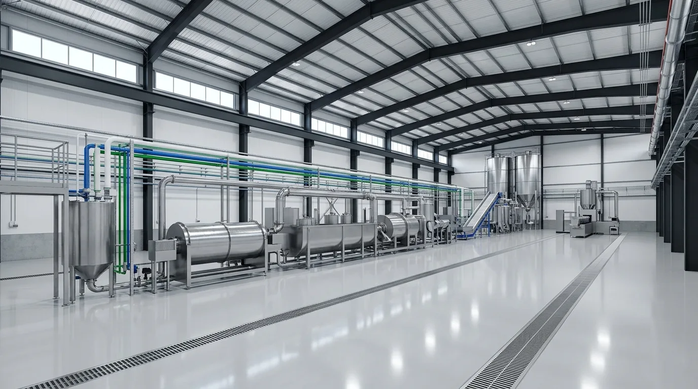
Plastic Recycling Plant Design Guide
12 min read