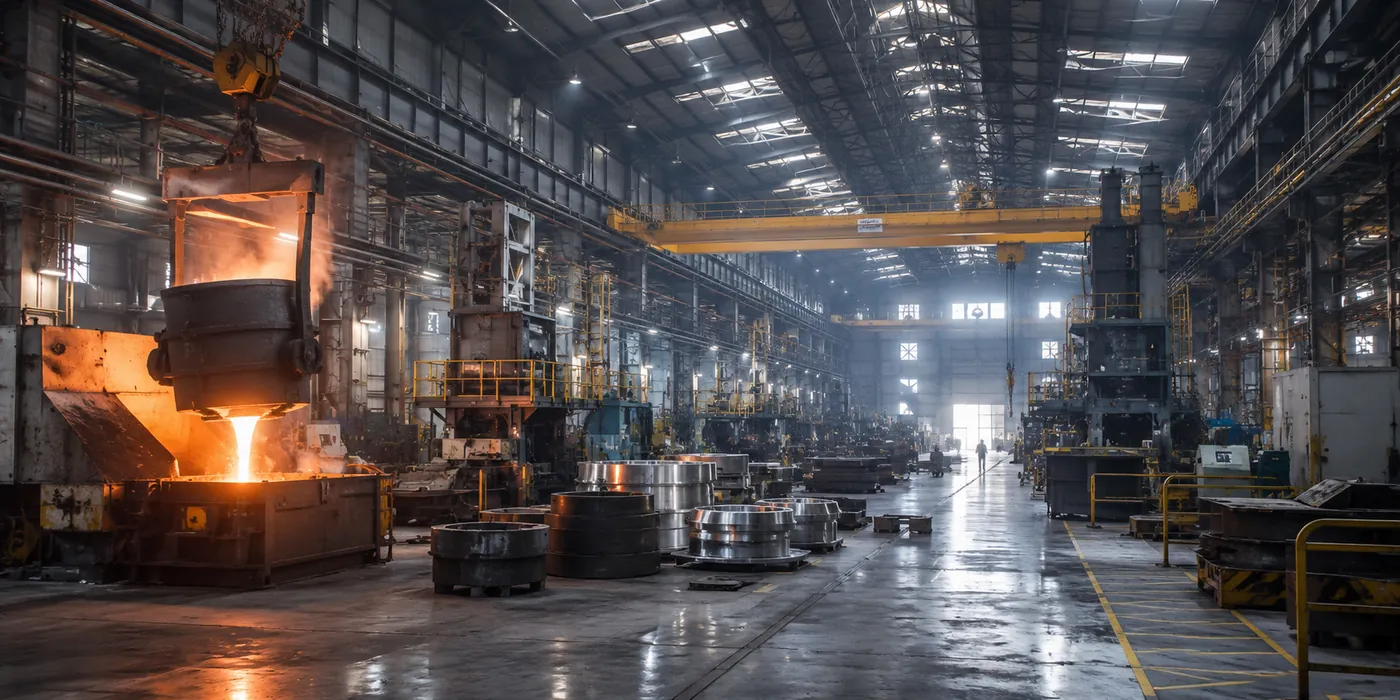
Grinding Media Foundry Campus, Ahmedabad
BACK TO HOME

Foundry — grinding media, high-chrome cast iron · Ahmedabad, Gujarat

Grinding Media Foundry Campus

Delivered for a leading grinding media manufacturer over 22 months.

Furnaces
3 melting + 3 holding
Heaviest crane
30 / 50 MT EOT
Clear height
15m, crane rail at 10m
HT supply
11 kV, 2 transformers

A 9.2-acre high-chrome cast iron foundry campus producing grinding media, delivered over 22 months. The facility runs three melting and three holding furnaces across two production lines, under EOT cranes up to 30 MT, fed by an 11 kV HT supply with layered redundancy.

Two problems shaped the design. Structurally and electrically, the building had to carry very heavy dynamic crane loads while guaranteeing that a furnace mid-melt was never exposed to a single point of power failure. Architecturally, a process running from above 1500°C down to hand-finishing had to be separated so that heat, fumes and fire risk never reached the people handling finished castings.

Plot area9.2 acres
Built-up areaapprox. 4,00,000 sq ft
StatusCompleted
Our scopeMaster Planning · Architecture · Structural Coordination · Electrical & MEP Coordination · Project Management Consultancy
01

Structural & Electrical

Heavy Crane Loads and HT Power

Engineering for 30 MT crane loads and 11 kV incoming supply across two furnace bays

The problem

The melting and holding furnace bays needed to support very heavy, dynamic crane loads — up to 30 MT on the melting platform alone — across a 15m clear-height shed, while keeping crane rail access at a workable 10m for maintenance. At the same time the plant needed a reliable 11 kV HT supply capable of feeding both continuous furnace loads and standby DG backup, without single points of failure that could halt a molten-metal process mid-cycle.

The solution

Structural frames were sized for the full crane duty cycle: three 10 MT plus one 30 MT EOT cranes and a 5 MT monorail on the melting platform, and two 10 MT plus two 5 MT EOT cranes on the holding furnace bay, with crane rail level fixed at 10m inside a 15m clear-height shed. Mezzanine floors at 3.5m were added at maintenance walkways and pouring areas without interrupting crane runway clearances. On the electrical side, 11 kV HT supply enters via underground cable to a metering kiosk with CT and PT, through an isolator with earth switch and gantry, into two main HT transformers. Seven internal distribution transformers with LT panels step down power for individual machine areas, backed by four 750 KVA DG sets, each with a dedicated diesel tank.

The outcome

A structural frame that carries its heaviest lift — 30 MT — with full maintenance access at a safe 10m crane rail height, and an electrical system with layered redundancy from HT metering through to DG backup, so a furnace in the middle of a melt is never exposed to a single power failure point.

02

Architectural

Space Planning for a Two-Line Foundry

Keeping hot process, finishing and utilities in separate zones across a linear production spine

The problem

A foundry moves metal through very different environments in one continuous flow — from a melting furnace at over 1500°C, through moulding and pouring, to a finishing area where workers handle the cooled casting by hand. If these zones are not physically separated, heat, fumes and fire risk from the melting and pouring areas spread into spaces where people work closely with the product, creating both a safety hazard and a quality risk from heat distortion.

The solution

The layout follows the process itself, not the plot shape. Melting and holding furnaces — the hottest and highest-risk zones — are grouped into their own dedicated bays, physically separated from the moulding, pattern-making and finishing areas by structural walls, not just distance. Molten metal only ever travels along a fixed, short crane path, from furnace to mould, never crossing a walkway or a finishing zone. Cooling and quenching, where the casting first becomes safe to handle, sits as a buffer stage between the hot zone and the finishing area, so nobody working on finished castings is ever standing next to an open furnace.

The outcome

Heat, fumes and fire risk stay contained to the two bays built for them, while moulding, finishing and quality checks happen in a separate, safer environment — with a fixed, minimum-distance path for molten metal designed once into the building, not managed afterwards through site rules.

Planning something similar?

Tell us the plot and the process, and you will get a specific answer rather than a brochure.