Executive Key Takeaways
- Start with the manufacturing process routing, cycle times, and batch sizes rather than the building perimeter.
- Plan operating, maintenance, and material loading envelopes for every machine—never rely on raw equipment footprints.
- Integrate clean utility drops (power, compressed air, coolant lines, data) directly into floor trenches or overhead busways.
- Provide isolated structural machine foundations to isolate precision equipment from ambient ground vibrations.
- Designate discrete zones for Raw Material, WIP buffers, Tool Pre-setting, CMM Quality Metrology, and Finished Goods.
- Build future expansion bays and scalable electrical capacities into the day-one masterplan.
Designing a precision machining unit is much more than deciding where to place CNC machines inside a factory building. A well-designed machining facility must bring together production planning, machine selection, process flow, material movement, quality control, utilities, safety, storage, maintenance and future expansion into one coordinated facility design.
Whether the proposed facility is for CNC turning, VMC machining, 5-axis machining, precision components, automotive parts, aerospace components, tool and die manufacturing or general engineering, the building should be designed around the manufacturing process—not the other way around.
A good machining plant layout allows materials to move efficiently, operators to work safely, machines to be maintained easily and the production system to expand without major disruption.
Start With the Manufacturing Process, Not the Building
One of the most common mistakes in factory planning is starting with the building footprint. For a precision machining facility, the first question must always be: What are we manufacturing, and how will each component move through the production process?
Before preparing the architectural layout, the design team must thoroughly understand the complete production parameters. Designing the building shell first forces machinery into sub-optimal orientations, creating bottlenecks that permanently degrade throughput.
- Products and components to be manufactured
- Annual and monthly production targets
- Product dimensions and individual component weights
- Material types (steel alloys, aluminium, brass, castings, forgings)
- Batch sizes and production volumes
- Machining operations and required cycle times per operation
- Number of operating shifts and planned equipment uptime
- Inspection requirements (in-process gauging vs CMM metrology)
- Outsourced processes (heat treatment, surface finishing, coating)
- Material handling requirements and future expansion horizons
Core Design Rule
The facility layout must be developed around the product routing. The building exists to protect and facilitate the manufacturing process—never the other way around.
Understand What "Precision Machining" Actually Requires
A precision machining unit brings together a complex suite of manufacturing technologies. Depending on the product portfolio, the facility may house a combination of CNC turning centres, vertical machining centres (VMC), horizontal machining centres (HMC), multi-axis systems, surface and cylindrical grinders, EDM/wire-cut equipment, and deburring systems.
Every machine tool has an equipment footprint, an operating envelope, a loading requirement, a maintenance access envelope, a structural foundation specification, and unique utility demands. Compiling this inventory early is non-negotiable.
- CNC Turning Centres & CNC Lathes
- Vertical Machining Centres (3-axis & 4-axis VMCs)
- Horizontal Machining Centres (HMCs with pallet changers)
- 5-Axis Precision Machining Centres
- Surface Grinding & High-Precision Cylindrical Grinding
- Electrical Discharge Machining (Die-sinking EDM & Wire EDM)
- Drilling, Tapping, Honing, and Broaching Equipment
- Automated Parts Washing & Ultrasonic Deburring Stations
- Tool Presetting Stations & Gauge Calibration Standards
- Coordinate Measuring Machines (CMM) and Optical Vision Systems
Prepare the Detailed Equipment Schedule
Once the manufacturing sequence is defined, prepare an engineering-grade equipment schedule. This data should originate directly from the machine tool manufacturers (OEM technical manuals) rather than generic approximations.
| Machine / Parameter | Design Implication | Why It Matters for Plant Design |
|---|---|---|
| Machine Name & Type | Functional Production Cell | Defines the operational role and position in process routing. |
| Overall Dimensions (L × W × H) | Floor Area Allocation | Establishes static footprint and clear ceiling height requirements. |
| Total Operating Weight | Structural Foundation | Critical for soil bearing capacity, dynamic loads, and foundation depth. |
| Connected Electrical Load (kW/kVA) | Power Infrastructure | Sizes transformer, busbar trunking, and DG backup capacities. |
| Compressed Air (CFM & Pressure) | Pneumatic Distribution | Determines compressor room sizing, air receiver, and loop piping. |
| Coolant & Lubrication Needs | Trenching & Drainage | Shapes coolant recycling, sump access, and spillage containment. |
| Loading Method & Door Heights | Material Handling Access | Sets aisle width, forklift clearances, or overhead crane hooks. |
| Maintenance Clearances | Service Envelope | Reserves access for spindle removal, hydraulic power units, and electrical cabinets. |
| Chip Disposal Mechanism | Waste Management Flow | Dictates conveyor clearance, bin swapping routes, and scrap staging. |
Design the Material Flow
Material flow is the circulatory system of a machining plant. A component should travel smoothly along a logical, unidirectional path without backtracking, unnecessary handoffs, or cross-traffic congestion.
For high-volume serial production, dedicated linear or U-shaped manufacturing cells work best. For high-mix, low-volume job shops, a flexible cellular arrangement balances short travel distances with agile changeovers.
Raw Material Receiving
Logistics dock, inspection of bar stock, billets, forgings, and castings.
Raw Material Storage
Cantilever racks, pallet staging, and automated bar feeders.
Cutting & Blank Prep
Band saws, circular saws, and material identification marking.
CNC Machining Cells
Turning, VMC, HMC, and 5-axis primary machining operations.
Secondary Operations
Drilling, tapping, grinding, EDM, and deburring.
Washing & Degreasing
Ultrasonic cleaning and parts drying before metrology.
Quality Inspection (CMM)
First-piece, in-process, and 100% final dimensional validation.
Finished Goods & Packing
Anti-corrosion coating, packaging, and dispatch staging.
Plan the CNC Machine Area Carefully
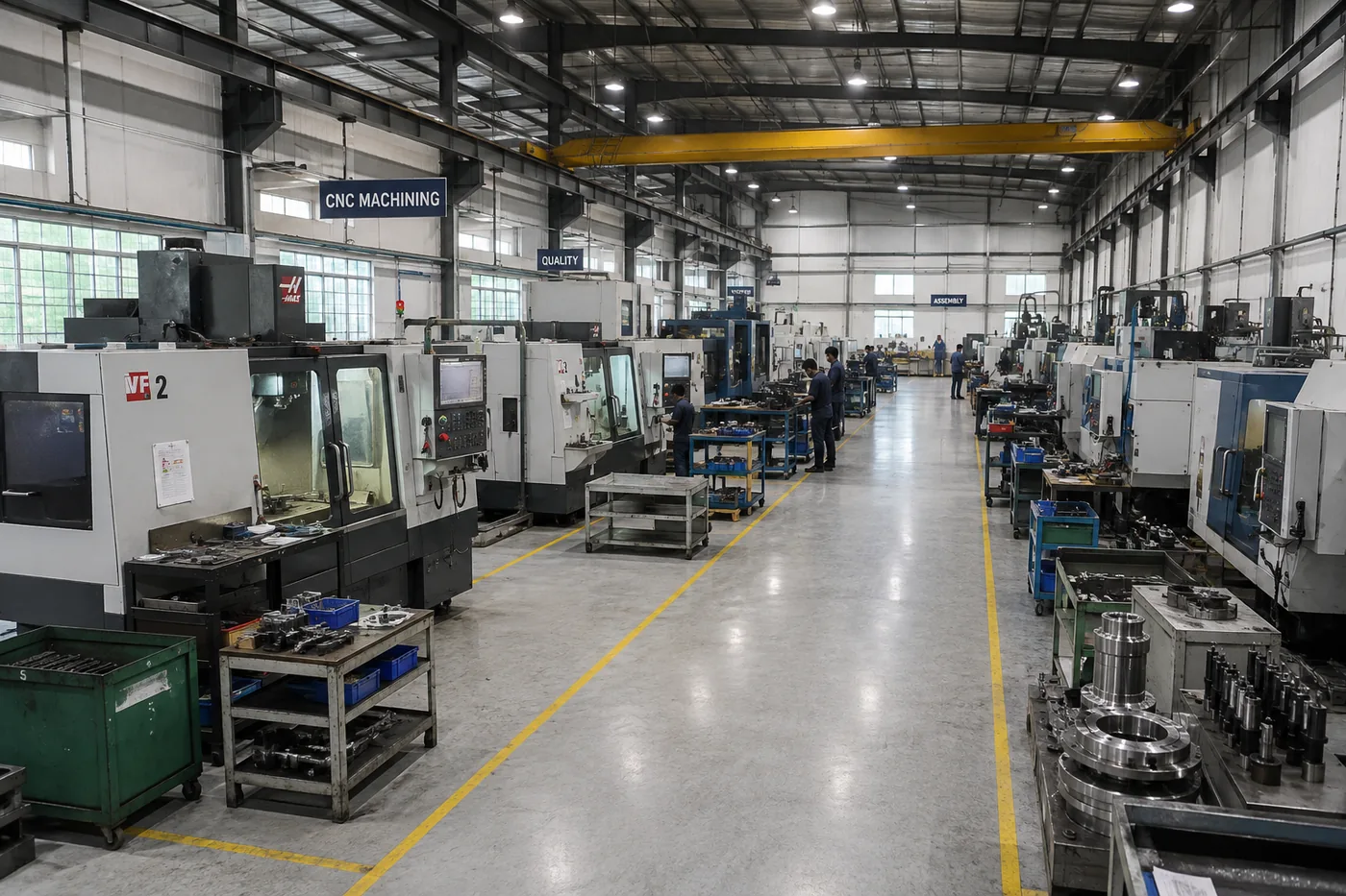
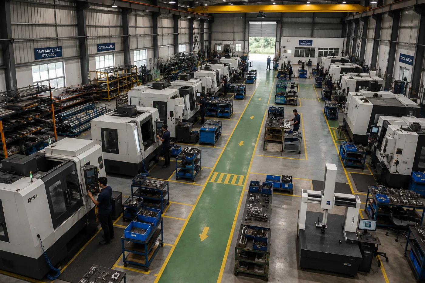
The CNC machining area forms the beating heart of the facility. Arranging machines purely in neat aesthetic rows is often inefficient. Machine layout must account for the complete operational and maintenance envelope.
Operators require ergonomic, unhindered access to CNC control panels, workpiece clamping fixtures, tool carousels, and in-process measuring instruments. Material handling equipment—whether manual pallet trucks, forklifts, or jib cranes—must load blanks without interfering with adjacent work centres.
Maintenance teams must be able to pull spindles, service hydraulic power packs, clean coolant sumps, and open electrical control cabinets without requiring neighbouring machines to cease production.
Crucial Clearances Rule
Machine Footprint ≠ Required Machine Area. Always add the operator operating zone, pallet staging area, and 360° maintenance envelope when calculating spatial allocations.
Create Dedicated Material Storage Areas
Poorly planned storage quickly spills over into production aisles, creating clutter, safety hazards, and lost components. A high-efficiency precision machining facility requires clearly demarcated, dedicated storage zones:
- Raw Material Storage: Dedicated cantilever racking for steel bars, aluminium extrusions, heavy pallets for forgings/castings, and billet racks.
- Work-in-Progress (WIP) Buffers: Allocated, visually marked staging areas between cutting, roughing, finishing, and washing stages.
- Tooling & Fixture Storage: High-density vertical carousels or modular tool cabinets for milling cutters, boring bars, inserts, and clamping fixtures.
- Finished Goods Storage: Clean, climate-protected staging zone for approved components awaiting dispatch packaging.
Plan the Tool Room and Tool Management Area
As machining tolerances tighten and cycle times accelerate, tool management directly influences spindle uptime. A dedicated tool room centralizes tool pre-setting, cutter regrinding, insert inventory, and fixture maintenance.
Locate the tool room centrally relative to the primary CNC bays. This minimizes operator transit time during tool changeovers without obstructing major material-handling thoroughfares.
Give Quality Control Its Own Design Logic
Precision manufacturing cannot be separated from quality assurance. Metrology planning requires a tiered approach based on measurement precision and sensitivity to ambient vibration, temperature, and airborne contaminants.
In-process inspection stations with height gauges and calipers can be stationed adjacent to machining cells. However, high-precision Coordinate Measuring Machines (CMM) and optical profilometers require a dedicated, climate-controlled inspection room.
- Strict temperature stabilization (typically 20°C ± 1°C) with dedicated HVAC.
- Isolated inertia foundation slabs to eliminate structural vibration transmission from nearby CNC mills or heavy presses.
- Positive air pressurization and airlock entry to keep out airborne coolant mist and metal dust.
Plan Utilities Around the Machines
CNC machine tools demand complex utilities that must be engineered into the floor and structural framework from day one. Retrofitting utilities post-construction leads to unsightly, hazardous cables and hoses draped across aisles.
- Electrical Distribution: Overhead sandwich busbar trunking systems or covered floor trenches with dedicated isolators and surge protection.
- Compressed Air: Ring-main aluminum or GI loop piping with dedicated moisture separators, refrigerated air dryers, and localized filter-regulator-lubricator (FRL) units.
- Coolant & Process Fluids: Centralized coolant distribution or dedicated pump-out stations with oil skimmers and filtration loops.
- Industrial Data & IoT: Shielded Ethernet and fiber connectivity for CNC DNC links, machine monitoring, and Industry 4.0 MES telemetry.
Don't Ignore Machine Foundations and Dynamic Loads
High-speed machining centres and heavy VMCs generate significant dynamic loads during rapid axis reversals. If mounted on standard industrial concrete slabs, machine vibration degrades surface finish accuracy and accelerates spindle bearing wear.
Consult machine OEM foundation guidelines early. High-precision machines often mandate isolated concrete inertia blocks with perimeter elastomeric dampening joints, heavy reinforcement mats, and precision leveling anchor bolts.
Plan Internal Roads and Material Movement
A busy machine shop experiences constant movement: forklifts hauling raw bars, operators moving trolleys, chip collectors carrying scrap, and inspectors transporting finished parts. Congestion increases cycle times and collision risks.
Design separate pedestrian pathways with bright floor coatings and demarcated crossing zones. Size forklift aisles based on vehicle turning radiuses plus minimum safety clearances as recommended by industrial safety codes.
Consider Temperature, Ventilation and Working Environment
Thermal expansion in steel and aluminium workpieces during temperature swings is one of the biggest causes of dimensional rejects. Machine motors and spindle drives also generate significant heat, while flood coolant produces oil mist.
Incorporate source-capture oil mist collectors on CNC enclosures. Implement natural cross-ventilation, evaporative cooling, or precision HVAC depending on component tolerance bands (aerospace and medical components generally require continuous climate control).
Plan Chip and Coolant Management
High-speed machining generates substantial volumes of metal swarf (chips) and spent coolant daily. If chip handling is treated as an afterthought, oily chips accumulate around machines and spill onto aisles.
Position chip conveyors discharging directly into rolling chip hopper bins. Plan a dedicated scrap segregation yard with oil-recovery centrifuge systems and covered scrap storage bays.
Design for Safety, Statutory Compliance and NBC 2016
Industrial facility designs in India must strictly adhere to the National Building Code of India (NBC 2016) and applicable State Factory Rules. Key compliance imperatives include:
- Fire & Life Safety (NBC Part 4): Adequate travel distances to emergency exits, fire hydrant rings, automatic sprinkler systems, and fire doors.
- Building Services (NBC Part 8): Minimum natural lighting ratios, artificial illumination lux levels across work zones, and ventilation air changes.
- Structural Safety (NBC Part 6): Seismic zone compliance, industrial wind load design, and heavy floor loading allowances.
- Worker Welfare: Clean changing rooms, sanitary facilities, ergonomic canteen spaces, and first-aid medical rooms.
Plan the Administrative and Support Areas
A precision machining facility requires tight coordination between management, CAD/CAM programmers, quality engineers, and shop-floor operators. Administrative spaces should be strategically connected to production.
Position the production office and CAM programming room with direct glass viewing windows overlooking the main machining bay. This provides visual control while shielding technical staff from shop-floor noise.
Think About Future Expansion Before Construction
Most machining enterprises start with 5 to 10 machines and plan to expand to 20, 30, or 50+ machines as client orders scale. If the initial masterplan fails to account for expansion, future growth requires expensive civil modifications and catastrophic production halts.
Plan modular building bays with knock-out end walls. Reserve spare electrical transformer capacity, space in compressed air headers, and extended crane runway girders during phase one.
A Typical Precision Machining Facility Organization
A well-orchestrated manufacturing plant integrates receiving, production, metrology, utilities, and dispatch into a continuous, unidirectional sequence:
Information Required Before Designing a Machining Facility
To eliminate assumptions and avoid costly redesigns, the engineering and architectural team should obtain the following data prior to final masterplan layout freezing:
Production Information
- Product component list, geometry, and material specifications
- Target annual, monthly, and daily output volumes per component
- Cycle times, number of setups, and number of shifts (1, 2, or 3)
- Component weight and batch handling lot sizes
Machinery & Utilities Data
- Complete OEM machine schedule with static and dynamic weights
- Connected power load (kW), voltage stability tolerances, and air consumption (CFM)
- Machine foundation drawings and anchoring details from OEM
- Crane hook height requirements and jib crane capacities
Logistics & Storage Data
- Raw material delivery vehicle types (trailers, flatbed trucks, light commercial vehicles)
- Finished goods dispatch container requirements
- Internal material handling equipment specifications (forklift type, turning radius)
- Days of inventory to be buffered for Raw Material, WIP, and Finished Goods
Critical Mistakes to Avoid in Facility Planning
1. Designing the building before understanding the process
A factory building must be molded around the manufacturing flow. Constructing a generic box first creates permanent operational inefficiencies.
2. Treating machines simply as rectangular footprints
Machines require substantial operational room, tool change clearances, maintenance access, and chip bin removal space.
3. Ignoring WIP staging buffers
Without planned WIP locations, intermediate batches accumulate in transit aisles, obstructing material handling equipment.
4. Leaving inspection as an afterthought
Placing CMM equipment in generic dusty shopfloor corners causes measurement errors and instrument calibration drift.
5. Inadequate electrical and utility planning
Under-sizing transformers or neglecting loop air distribution creates voltage drops and pneumatic pressure fluctuations that trip machines.
6. Lack of vibration isolation on foundations
Failing to isolate precision VMCs from forging presses or external truck roads leads to surface chatter and tolerance failures.
7. Neglecting chip and coolant logistics
Chip bins that must be wheeled through narrow operator zones create safety hazards and waste operator time.
8. Zero provision for modular expansion
Building without modular expansion zones forces expensive demolition or fragmented secondary facilities later.
The Bottom Line: Process-Driven Facility Planning
Designing a precision machining unit is fundamentally a process-planning and facility-planning exercise, not simply an architectural exercise. The most successful facilities start with the manufacturing process and work outward.
When production routing, spatial requirements, machine foundations, utilities, safety, and future scalability are coordinated early, the resulting factory delivers superior operational efficiency, lower lifecycle costs, and higher worker productivity.
At Vishwakalpa Design, Planning & Management, we approach industrial facility planning by understanding your manufacturing process first, translating your production targets into an optimized masterplan, high-performance architectural layout, and turnkey engineering design.
Frequently Asked Questions
How much space is required for a precision machining unit?
There is no single universal square footage. Area depends on the machine count, machine models, material handling systems, raw material buffer policies, CMM quality inspection requirements, utilities, and administrative spaces. A 10-machine unit typically requires 1,000–1,700 m² (10,700–18,300 sq.ft) of built-up area, but this must be calculated from a detailed equipment schedule.
How should CNC machines be arranged in a plant layout?
Machine arrangement should follow the product routing. Linear, U-shaped cellular, or hybrid layouts can be used depending on whether the production model is high-volume serial or high-mix job-shop. Crucially, layouts must provide clear operator access, forklift clearance, and full maintenance envelopes around each machine.
Does a precision machining plant need a dedicated CMM room?
For precision machining (tolerances under 10–20 microns, aerospace, medical, or automotive tier-1 parts), a dedicated climate-controlled CMM room (20°C ± 1°C) with an isolated inertia foundation slab is strongly recommended to eliminate temperature-induced part expansion and structural vibration.
What information is needed before designing a CNC facility?
Key inputs include the product drawings, material types, monthly production targets, complete OEM machine tool specs (weight, dimensions, power kW, CFM), material handling methods, storage buffer targets, and 5-to-10-year expansion forecasts.
Why are special foundations required for CNC machines?
High-speed CNC machines generate significant dynamic inertial forces during axis acceleration and deceleration. Special reinforced concrete foundations with vibration dampening joints prevent vibration transmission from surrounding equipment and ensure micron-level cutting accuracy.
How does Vishwakalpa assist with precision machining plant design?
Vishwakalpa provides end-to-end industrial master planning, process-driven plant layouts, structural engineering, MEP and utility integration, statutory compliance under NBC 2016, and Project Management Consultancy (PMC) across India.

Explore More Technical Guides
CNC Machining Plant Layout Planning Guide
14 min read
CNC Plant Space Requirement Calculation Guide
15 min read
What Is Industrial Architecture?
10 min read
Foundry Layout Planning Guide
14 min read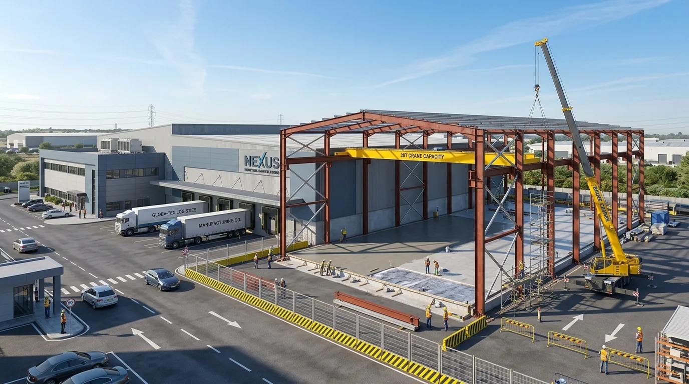
Plant Expansion Readiness Guide
11 min read