Executive Key Takeaways
- Choose the right layout topology: Functional (job shop), Product Line (high volume), Cellular (part families), or Hybrid.
- Map the complete component journey before freezing machine positions to eliminate backtracking and long forklift travel.
- Provide dedicated, marked transit aisles with clear pedestrian separation to prevent workplace hazards.
- Deliberately size and locate WIP staging buffers at each stage of the process to avoid floor clutter.
- Coordinate structural building grids and column locations with overhead crane hooks and machine loading zones.
- Utilize digital layout modeling and simulation to validate material travel and bottleneck prevention prior to construction.
A CNC machining plant is not simply a large industrial building filled with machines. The way CNC machines, raw materials, tooling, inspection areas, storage, utilities and material-handling routes are arranged has a direct impact on production efficiency, operator productivity, safety, maintenance and future expansion.
A good CNC plant layout makes the movement of a component through the manufacturing process as simple, fast, and predictable as possible.
The fundamental question is not "Where can we fit all the machines?" It is: "How should the factory be arranged so that the product moves seamlessly from raw stock to finished component?"
Start With the Production Process
The first step in CNC plant layout planning is to map the exact manufacturing sequence. Before drawing walls or placing machines, the engineering team must establish product dimensions, batch sizes, cycle times, and operational routing.
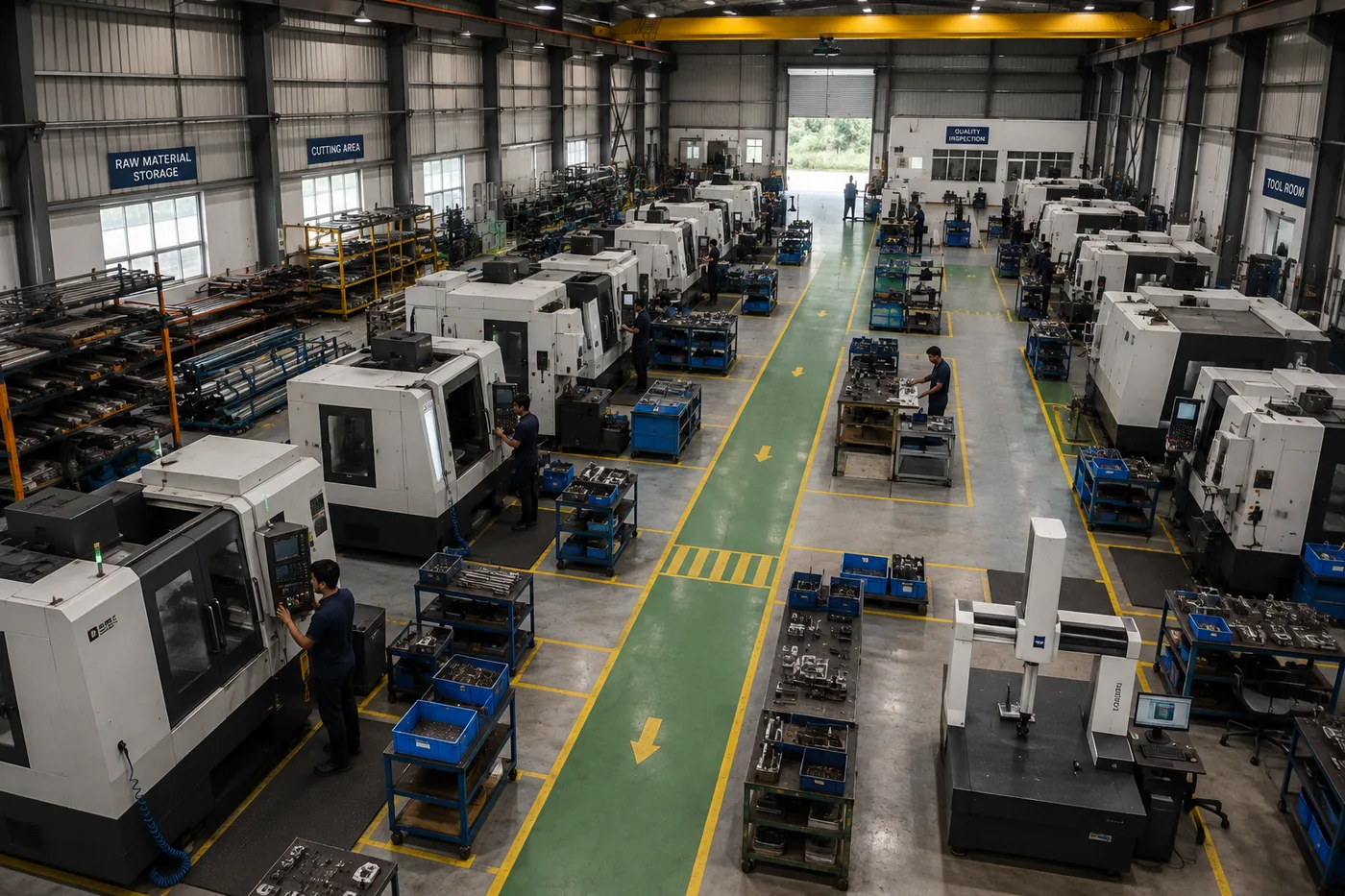
A typical precision machining routing flows from Raw Material Receiving → Raw Material Storage → Cutting → CNC Turning / VMC → Secondary Operations → Washing / Deburring → Inspection → Finished Goods → Packing & Dispatch. The plant layout must reflect this flow directly.
Prepare a Comprehensive Machine and Equipment List
Compile a complete inventory across all equipment categories. Include primary machining tools (turning centres, VMCs, HMCs, 5-axis mills, grinders, EDMs), supporting systems (tool presetters, washing units, chip conveyors, air compressors, chillers), and metrology instruments (CMMs, height masters, surface testers).
For each asset, obtain precise OEM specs for dimensions, dry weight, electrical requirements, pneumatic CFM, foundation depth, door swing clearances, and maintenance access.
Map the Material Flow Before Placing Machines
Track the journey of a workpiece from the moment raw steel bars or castings enter the receiving dock until finished components are loaded onto dispatch trucks.
Industrial engineering research consistently proves that minimizing material travel distance and eliminating cross-traffic reduces cycle times, minimizes transit damage, and prevents forklift congestion.
Layout Golden Rule
Process flow should drive machine placement—not the architectural building envelope. Minimize total meters traveled per component.
Choose the Right Layout Strategy
Different machining business models require distinct spatial layouts:
- Functional Layout: Machines performing similar processes are grouped together (all CNC lathes in one bay, all VMCs in another, grinding in a third). Ideal for high-mix, low-volume job shops with unpredictable routing.
- Product / Line Layout: Machines are arranged in the sequential order of a specific high-volume product line. Highly efficient for dedicated automotive or repetitive component manufacturing.
- Cellular Layout: Machines required to manufacture a specific family of components are grouped into self-contained cells (e.g., Turning + VMC + Washing + Gauging in one U-shaped cell). Drastically cuts transit time.
- Hybrid Layout: The most popular modern configuration—combining dedicated high-volume machining cells with shared central services (central tool room, CMM metrology, and common raw material/dispatch docks).
Create a Logical CNC Machine Arrangement
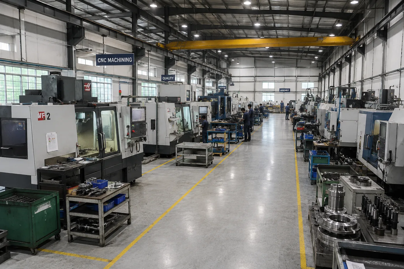
Machine layout requires substantially more space than the static dimensions shown on catalogue sheets. Every CNC machine requires dedicated space for the operator station, raw workpiece loading, finished part staging, tool changer access, rear electrical cabinet opening, coolant tank pump-out, and chip conveyor clearance.
Plan the Main Material-Handling Aisles
Aisles serve as the arterial highway of the factory. Size aisles according to the largest handling equipment (counterbalance forklifts, electric reach trucks, or tugger trains) plus safety margins.
Avoid arbitrary standard widths. A forklift carrying a 6-meter steel bar around a 90-degree corner requires a significantly wider turning corridor than a pedestrian pushing a small tool trolley.
Separate Pedestrian and Material Movement Wherever Practical
Co-mingling heavy forklift traffic with walking machine operators creates continuous collision risks. Modern plant design establishes dedicated pedestrian walkways marked with high-visibility epoxy floor coatings, pedestrian barriers, and clearly signed intersection crossings.
Locate Raw Material Storage Strategically
Position raw material storage adjacent to the unloading bay and the primary cutting operations. Heavy bar stock, billets, and castings should not be hauled through central machining corridors before initial blank sizing.
Don't Forget Work-in-Progress (WIP) Storage
WIP is often the greatest hidden space consumer in machining facilities. When components wait between operations without designated staging buffers, they accumulate randomly around machines, blocking access and creating confusion.
Calculate required buffer sizes based on batch release policies and allocate designated, numbered floor squares for WIP pallets.
Plan the Tool Room Around Production
The tool room should be centrally positioned relative to the primary CNC bays. Placing it too far increases operator walking time during tool setup; placing it in a high-traffic forklift artery creates congestion.
Integrate Quality Control Into the Layout
Quality control should not be an isolated room at the far end of the plant. In-process inspection stations should be distributed near production cells, while the precision CMM laboratory should sit logically between machining and final packaging.
Consider Machine Foundations and Structural Requirements
Coordinate machine locations with structural slab thickness, soil bearing capacity, and vibration isolation requirements. Heavy 5-axis machines or grinding equipment must not bridge expansion joints or sit over utility ducts.
Coordinate Utilities With the Machine Layout
Design utility drops (electrical busbar tap-offs, compressed air drops, chilled water, and industrial Ethernet) directly above or beneath machine connection points. This avoids hazardous surface cables and pipes.
Plan for Chip and Coolant Movement
Ensure chip removal routes lead directly to an exterior scrap collection yard without passing through clean inspection or administrative zones. Incorporate central coolant filtration or dedicated fluid replenishment stations.
Plan Loading and Unloading Areas
Design logistics docks to accommodate target truck profiles (multi-axle trailers, container trucks, light commercial vehicles). Ensure adequate exterior turning aprons and grade-level ramp access.
Consider Columns and Structural Grid Early
Coordinate building column spacing (e.g., 18m × 24m or 12m × 18m spans) so columns do not land within forklift turning lanes, overhead crane hook envelopes, or machine maintenance access zones.
Design the Factory for Maintenance
Ensure every machine has sufficient perimeter clearance to open 90° electrical cabinet doors, remove spindles, service hydraulic power packs, and replace ballscrews without shutting down neighboring machines.
Plan for Future CNC Machines
Reserve modular floor bays, spare capacity in electrical busways, compressed air ring mains, and structural capacity in crane girders so phase-two machines can be commissioned without disrupting live operations.
Use a Space Program Matrix Before Drawing Layouts
Develop a rigorous space program matrix allocating area based on calculated operational requirements rather than arbitrary percentages:
| Functional Zone | Primary Function | Key Considerations |
|---|---|---|
| Receiving & Unloading | Incoming Raw Stock & Billets | Dock levellers, crane coverage, inspection staging. |
| Raw Material Storage | Long Bar & Heavy Billet Inventory | Cantilever racks, heavy floor loading capacity. |
| Cutting & Blank Prep | Saws & Blank Sizing | Positioned immediately adjacent to raw stock. |
| Core CNC Machining | Turning, VMC, HMC, 5-Axis | Power busways, air drops, foundation isolation, chip bins. |
| Secondary Operations | Grinding, Honing, EDM, Deburring | Vibration isolation, dust capture, fluid containment. |
| Parts Washing | Ultrasonic & Degreasing | Ventilation exhaust, drainage, water supply. |
| Quality Metrology / CMM | Dimensional & Surface Testing | 20°C climate control, isolated inertia foundation. |
| Tool Room & Stores | Presetting, Cutters & Fixtures | Central location, high-density secure storage. |
| WIP Storage Buffers | Inter-operational Inventory | Clearly demarcated floor squares near cells. |
| Finished Goods & Packing | Packing & Dispatch Staging | Clean zone, packaging supplies, weighing scale. |
| Plant Utilities | Compressor, DG, Transformer, Chiller | Acoustic isolation, exterior service access. |
| Administration & Welfare | Offices, CAM Room, Canteen, Restrooms | Overlooking shopfloor, noise-attenuated. |
| Future Expansion Bay | Phase-2 Machine Additions | Pre-stubbed utilities, modular structural bay. |
Evaluate More Than One Layout Option
Develop and compare multiple spatial options (e.g., Option A: Linear Flow, Option B: Cellular Layout, Option C: Hybrid Configuration). Score each option across material travel distance, space efficiency, safety, utility complexity, capital expenditure, and future expansion flexibility.
Consider Digital Layout Analysis for Larger Facilities
For facilities with 20+ machines or automated guided vehicles (AGVs), digital layout modeling and throughput simulation can reveal invisible bottlenecks, queue accumulation, and forklift conflicts before construction commits capital.
Don't Treat Safety and Compliance as an Afterthought
Incorporate National Building Code of India (NBC 2016) provisions and State Factory Rules from the outset. Verify emergency exit travel distances, fire extinguisher and hydrant layouts, ventilation rates, and natural daylight factors.
Common CNC Plant Layout Mistakes to Avoid
Review this checklist to avoid the most frequent design pitfalls encountered in precision machining plants:
Critical Mistakes to Avoid in Facility Planning
1. Designing the building first
Fitting process flow into a pre-existing generic box creates irreversible bottlenecks.
2. Arranging machines simply in rows
Aesthetically pleasing straight rows often cause massive part travel and backtracking.
3. Ignoring WIP buffers
Unplanned intermediate inventory spills into transit aisles, blocking forklift corridors.
4. Insufficient maintenance access
Packing machines too tightly prevents spindle changes and hydraulic servicing.
5. Mixing pedestrian and forklift movement
Shared pathways without physical or visual barriers lead to severe safety hazards.
6. Inadequate utility routing
Neglecting overhead busways and floor trenches leads to hazardous draped cables.
7. No expansion strategy
Failing to reserve modular expansion bays causes expensive future disruptions.
8. Using generic machine clearances
Every machine OEM has unique service envelopes that must be accounted for individually.
9. Treating inspection as an afterthought
CMMs require isolated climate and vibration control, not a random corner.
10. Optimizing only for minimum floor area
The smallest footprint is rarely the most productive, safe, or scalable facility.
Practical CNC Plant Layout Workflow
Effective CNC facility planning follows a disciplined 10-step sequence: Understand Products → Map Process Flow → Determine Capacity → Prepare OEM Machine Schedule → Calculate Spatial Footprints & Clearances → Design Material Flow & Aisle Circulation → Allocate Storage & WIP Buffers → Integrate Utility & Foundation Grids → Incorporate Safety & NBC Compliance → Build Modular Expansion Zones.
At Vishwakalpa Design, Planning & Management, our multidisciplinary team of industrial architects, structural engineers, and MEP specialists translates manufacturing processes into world-class, high-efficiency machining facilities.
Frequently Asked Questions
What is the best layout for a CNC machine shop?
There is no single best layout for every plant. High-volume serial production benefits most from dedicated product lines or U-shaped cells. High-mix, low-volume job shops operate best with flexible cellular or hybrid layouts combining dedicated cells with shared tool room, quality CMM, and material storage zones.
How wide should forklift aisles be in a CNC machining plant?
Aisle width depends on the specific handling equipment (counterbalance forklift vs reach truck), pallet dimensions, and turning radii. Typical standard counterbalance forklift aisles require 3.5m to 4.5m of clear width, plus designated pedestrian walking paths.
How do you prevent vibration transmission to precision CNC machines?
Precision CNC machines (VMCs, 5-axis, and grinding machines) require isolated reinforced concrete inertia blocks separated from the surrounding factory floor slab by elastomeric expansion joints (such as cork, neoprene, or high-density foam).
What are the fire safety requirements for CNC machine shops under NBC 2016?
NBC 2016 Part 4 mandates maximum travel distances to emergency exits (typically 30m in industrial occupancies without sprinklers, or 45m with automatic sprinklers), fire-rated doors, peripheral fire engine access roadways, and dedicated fire hydrant loops.
How does Vishwakalpa design CNC factory layouts?
Vishwakalpa analyzes your part routings, OEM machine specifications, logistics volumes, and utility loads to develop optimized 2D/3D plant layouts, civil structural drawings, MEP utility trenches, and complete project management.

Explore More Technical Guides
Precision Machining Unit Design Guide
12 min read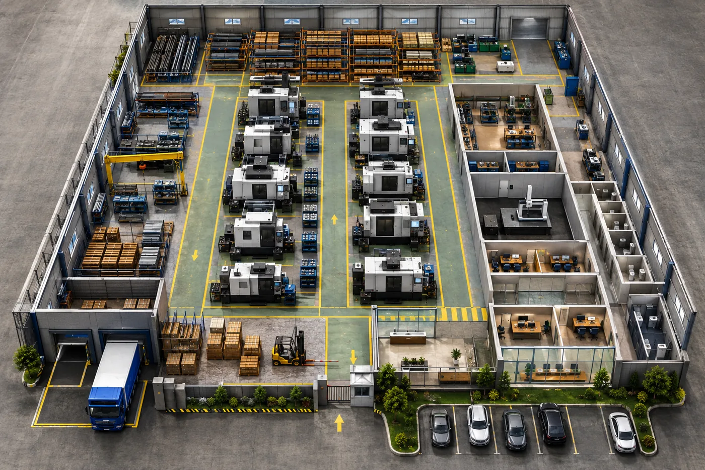
CNC Plant Space Requirement Calculation Guide
15 min read
What Is Industrial Architecture?
10 min read
Foundry Layout Planning Guide
14 min read
Plant Expansion Readiness Guide
11 min read