Executive Key Takeaways
- Aggregate connected loads across all machines and apply empirical diversity factors (0.65 to 0.80) to accurately size HT transformers, switchgear, and DG backup.
- Design compressed air piping as a continuous closed-loop ring main with 1:100 downward drainage slopes and top-takeoff gooseneck drops to eliminate terminal pressure drops and moisture contamination.
- Segregate industrial process cooling loops from comfort HVAC chillers to prevent cross-contamination and thermal cycling disruptions.
- Physically isolate industrial effluent (oil, chemicals, heavy metals) from domestic sewage, routing streams through neutralization sumps and oil-water separators to satisfy Zero Liquid Discharge (ZLD) norms.
- Establish a centralized Utility Block with dedicated pipe bridges or accessible underground walk-through trenches, preserving 30% reserve structural bracket capacity for Phase 2 scaling.
- Calculate all utility capacities directly from manufacturer machine datasheets rather than generic square-footage rules of thumb.
An industrial manufacturing facility cannot operate without its critical engineering lifeblood: high-voltage power distribution, clean compressed air, continuous cooling water loops, chemical drainage, and factory ventilation. Yet in many new factory builds, utilities are treated as an afterthought—retrofitted into whatever leftover space remains after the building shell is erected.
Late utility planning inevitably leads to severe operational compromises: undersized electrical transformers that trip during peak shifts, costly pressure drops along dead-end compressed air headers, uninsulated pipes condensing over finished goods, and complex piping routes that block overhead EOT cranes.
Effective industrial plant utility planning requires an integrated mechanical, electrical, and plumbing (MEP) approach rooted in primary equipment schedules. This guide outlines the engineering fundamentals of planning factory utilities from concept to commissioning.
Integrated Utility Planning Principles: The Process-First Approach
Utility engineering begins with a detailed Equipment Load Schedule (ELS). Every machine on the shopfloor—whether a 5-axis CNC machining center, an induction melting furnace, an injection molding press, or an automated packaging line—has specific consumption profiles:
- Electrical: Connected load (kW/kVA), running voltage (415V 3-phase vs 230V single-phase), starting inrush currents, and power factor.
- Pneumatic: Free Air Delivery (FAD) demand in CFM/Nm³/hr, minimum operating pressure (typically 6.0 to 8.5 bar), and air quality purity classes under ISO 8573-1.
- Thermal & Cooling: Heat rejection rates (kcal/hr or TR), required coolant flow rates (LPM), and inlet/outlet temperature deltas (e.g., 32°C supply / 37°C return for cooling towers).
- Process Water & Drainage: Softened water feed requirements, daily makeup volumes, chemical blowdown characteristics, and oily wash-water volumes.
Electrical Infrastructure: HT Substation, Transformers & DG Sync
Industrial manufacturing plants typically draw power from regional electric utilities at High Tension (HT) voltage levels—commonly 11 kV, 22 kV, or 33 kV. Transforming and distributing multi-megawatt power requires careful planning of incoming yards, metering kiosks, and indoor substations.
Transformer sizing must account for both instantaneous peak demand and future expansion. Simply summing machine nameplate ratings leads to massive over-sizing and poor transformer efficiency. Instead, engineers apply a diversity factor (the ratio of peak simultaneous demand to total connected load, typically 0.65 to 0.75 in general manufacturing):
| Substation Element | Typical Sizing Formula / Standard | Engineering Best Practice |
|---|---|---|
| Transformer Capacity | Contract Demand (kVA) = (Sum of Connected kW × Diversity Factor) / Power Factor | Select dual-transformer N+1 configurations (e.g., 2 × 1,500 kVA instead of 1 × 3,000 kVA) to prevent single-point downtime. |
| HT Metering & Isolator | Indoor VCB (Vacuum Circuit Breaker) or Outdoor Gantry with CT/PT | Provide isolation air-break switches with earth blades outside the boundary fence per state electricity board norms. |
| Power Factor Correction | Automatic Power Factor Correction (APFC) capacitor banks | Maintain power factor at 0.98 to 1.00 lag to avoid state utility penalties and maximize line capacity. |
| DG Standby Generation | 100% critical process loads + 50% auxiliary loads | Use auto-mains failure (AMF) and PLC-based auto-synchronizing panels for multi-DG parallel sharing. |
| Harmonic Filtration | Active Harmonic Filters (AHF) at variable frequency drives (VFDs) | Ensure Total Harmonic Distortion (THD) remains below 5% per IEEE 519 standards to protect sensitive electronics. |
Compressed Air Systems: Sizing, Ring Mains & Moisture Control
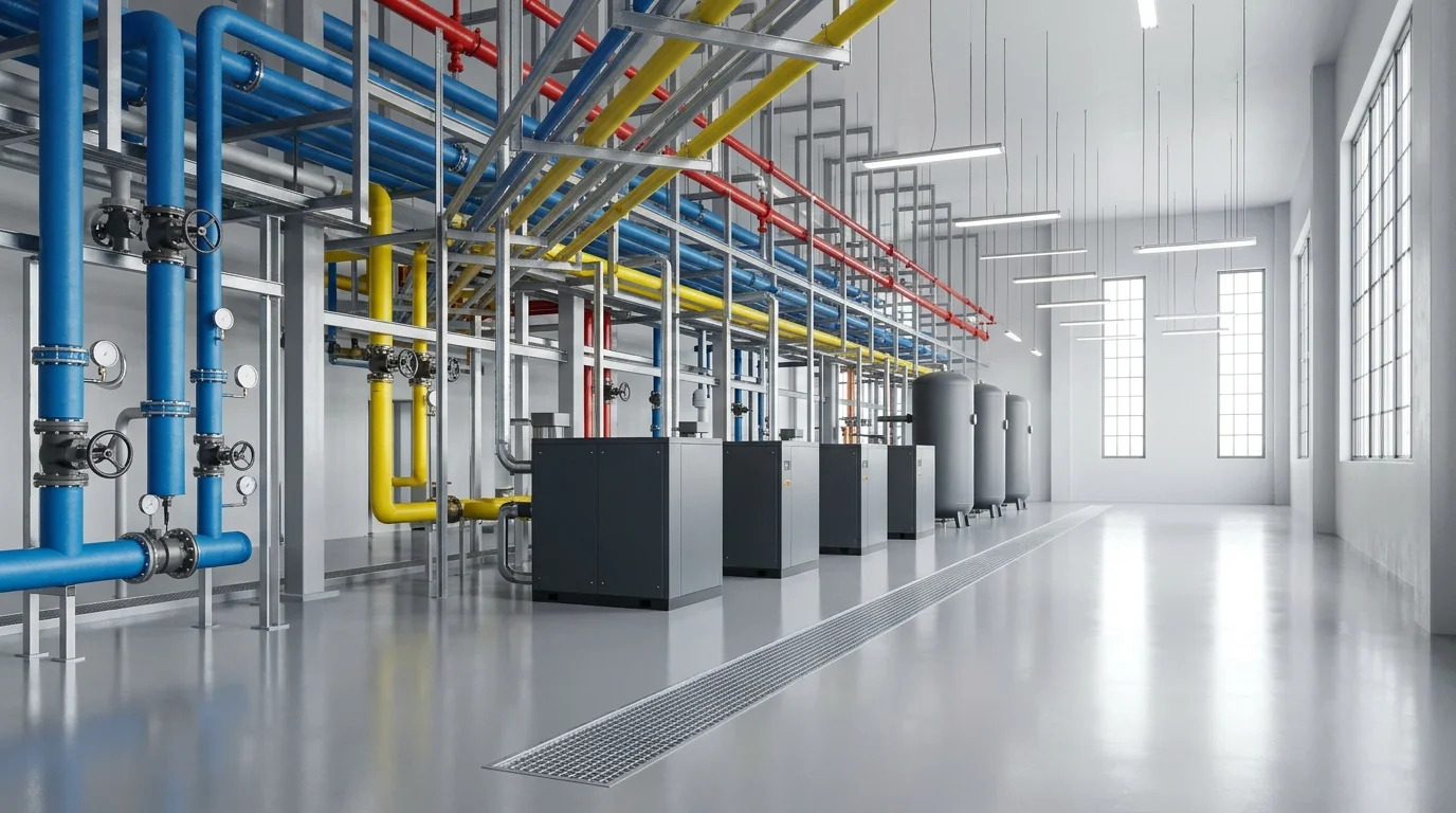
Compressed air is often called the fourth utility. It is also the most expensive utility to generate—roughly 85% of electrical energy input into a compressor is converted directly into waste heat, leaving only 15% as pneumatic energy. Inefficient piping layouts and pressure drops multiply these operating losses exponentially.
Best-practice industrial pneumatic distribution relies on three core design rules:
- Closed-Loop Ring Main Piping: Instead of a straight dead-end header that starves machines at the far end of the plant, route compressed air as a continuous closed loop around the plant perimeter. This allows air to flow from two directions simultaneously, cutting pressure drops by more than 50%.
- Moisture Drainage & Gooseneck Drops: Main headers should slope 1:100 in the direction of airflow, terminating in automatic moisture drain traps. Sub-headers feeding individual machines must always branch from the top of the main line (gooseneck / swan neck takeoff) to prevent condensed moisture from draining into machine valves.
- Air Quality & Dryers: Specify refrigerated dryers for standard 3°C pressure dew point (ISO 8573-1 Class 4 for general machine tools) or desiccant dryers for -40°C dew point in food, pharmaceutical, and cleanroom applications.
- Piping Materials: Replace traditional mild steel / galvanized iron (GI) piping with modular extruded aluminum piping. Aluminum eliminates internal corrosion, maintains smooth laminar airflow with minimal friction coefficient, and allows rapid push-fit modifications.
Industrial Water: Softening, Chilled Loops & Cooling Towers
Water is utilized in factories across three distinct hydraulic circuits: raw sanitary utility water, softened cooling circuit makeup, and closed-loop chilled process water. Mixing these circuits creates scaling, bio-fouling, and thermal instability.
Cooling systems generally fall into two primary configurations:
- Open-Loop Cooling Towers: Sized for high-heat industrial equipment such as furnace jackets, air compressor aftercoolers, and hydraulic power units. Requires automatic chemical dosing (anti-scalant, biocide) and continuous total dissolved solids (TDS) blowdown control.
- Closed-Loop Water Chillers: Required for precision processes that demand constant low-temperature coolant (e.g., CNC spindle chillers at 18°C–22°C or plastic injection mold chilling at 12°C). Sized with insulated stainless steel or HDPE headers, plate heat exchangers (PHE), and dual variable-frequency primary/secondary circulation pumps.
Effluent & Drainage Architecture: Industrial vs Domestic Streams
Modern environmental regulations enforced by the Central and State Pollution Control Boards (CPCB/SPCB) mandate strict Zero Liquid Discharge (ZLD) or compliant treatment before disposal. Cross-connecting factory floor drains to domestic storm drains is an immediate regulatory violation.
Plant drainage must be segregated into three independent collection systems:
- Domestic Sewage (Black & Grey Water): Handled via PVC/SWR pipes leading to an on-site Sewage Treatment Plant (STP). Treated tertiary water is reclaimed for landscaping and toilet flushing.
- Industrial Trade Effluent: Sourced from machine washing, component degreasing, chemical rinse tanks, and paint shops. Routed through acid-resistant HDPE/PP piping into an Effluent Treatment Plant (ETP) featuring equalization, chemical coagulation, flocculation, clarifiers, and multi-grade pressure sand/carbon filters.
- Oily Water Drainage: Compressor room runoff and machine maintenance pits must pass through an Oil-Water Separator (OWS) with coalescing media plates before entering the ETP.
Factory Ventilation & Industrial HVAC Heat Load Balancing
Manufacturing plants generate enormous internal sensible heat loads from electric motors, smelting furnaces, curing ovens, and solar heat radiation through large metal roofs. A plant designed without adequate thermal air exchange will experience unbearable 45°C+ indoor summer temperatures, impairing worker productivity and causing electronics overheating.
Ventilation planning combines passive architectural features with mechanical systems:
- Continuous Ridge Monitors: Roof-mounted aerodynamically shaped natural ventilators utilize the stack thermal effect (hot air buoyancy) to exhaust massive volumes of heat continuously without power consumption.
- High-Volume Low-Speed (HVLS) Fans: Ceiling-mounted large-diameter fans (5.5m to 7.3m diameter) move non-turbulent air columns across the shopfloor, producing a 4°C to 6°C perceived evaporative cooling effect for operators.
- Forced Mechanical Exhaust & Dust Extraction: High-heat zones (such as heat treatment ovens and welding bays) require targeted source capture hoods with centrifugal exhaust blowers and baghouse dust collectors discharging clean air through 30m statutory stacks.
Central Utility Blocks vs Pipe Racks: Distribution Topologies
Where should industrial utilities be housed? Scattering air compressors, water chillers, pumps, and electrical panels randomly across the production floor creates acoustic noise, vibration, maintenance hazards, and valuable floor space loss.
World-class industrial facility master planning isolates noisy and vibration-heavy machinery into a dedicated, centralized Utility Block situated adjacent to the main production sheds. Utilities travel between buildings along structured distribution spines:
- Overhead External Pipe Bridges: Structural steel trestles spanning between buildings at minimum 5.5m clearance to allow heavy container trucks and fire tenders to pass freely underneath.
- Internal Utility Corridors & Racks: Pipe racks supported from PEB portal columns, positioned above crane runway level (or under crane brackets with strict safety clearance) with organized tier separation: electrical cable trays on top, pneumatic lines in the center, and liquid water pipes at the bottom.
- Accessible Concrete Service Trenches: Walkable underground utility trenches with removable galvanized steel grating or precast concrete slabs, providing leak-proof containment and easy cable pull access.
Designing for N+1 Redundancy & Future Expansion Spines
A well-engineered manufacturing plant is designed for future scaling from day one. Retrofitting an extra 2,000 CFM compressor or a second HT transformer years later becomes an engineering nightmare if space and connection vectors were not preserved.
Key expansion provisions include:
- N+1 Utility Sizing: Providing an extra standby air compressor and cooling pump so routine preventative maintenance can be conducted during live production without throttling plant capacity.
- Pre-Flanged Utility Headers: Installing blinded flange tees and isolation gate valves on all main steam, water, and compressed air headers at the building expansion boundary.
- Spare Feeder Breakers: Reserving 25% to 30% spare breaker cubicles on Main Low Tension (MLT) distribution panels to accommodate future machine additions without replacing switchboards.
Critical Mistakes to Avoid in Facility Planning
1. Sizing utilities using generic square-foot thumb rules
Industrial power, air, and water requirements depend entirely on specific machine process schedules. Rule-of-thumb estimates lead to costly undersized transformers or wasted capital on oversized chillers.
2. Installing dead-end compressed air headers instead of closed ring mains
Creates severe terminal pressure drops of 1.5 to 2.5 bar, causing machine tool emergency stops whenever heavy pneumatic consumers activate.
3. Mixing sanitary sewage with industrial wash and compressor runoff
Violates environmental CPCB/SPCB regulations and overwhelms domestic STPs with oil and heavy metals, risking statutory plant closure.
4. Routing utility piping through overhead crane operating envelopes
Results in crane hooks and hoisted loads colliding with fragile water pipes, steam lines, or cable trays, posing catastrophic safety risks.
5. Overlooking acoustic and vibration isolation in utility blocks
Bolting heavy reciprocating or screw compressors directly to shared foundations transfers structural vibration into high-precision CNC machine beds and CMM metrology rooms.
Design Your Factory Utilities as an Integrated Engine of Production
Industrial utilities are not auxiliary afterthoughts—they are the critical infrastructure that determines your plant's operating cost, equipment longevity, and uptime reliability.
Engineering Disclaimer: Specific transformer capacities, piping diameters, cable sizing, and environmental treatment requirements must always be calculated from actual vendor equipment datasheets, soil thermal resistivity tests, and statutory pollution board norms. Vishwakalpa coordinates directly with your process vendors to engineer safe, optimized utility networks.
Frequently Asked Questions
How do you calculate the electrical connected load for a new manufacturing facility?
Calculate electrical load by tabulating the continuous kW rating of every machine, lighting circuit, and auxiliary motor, then applying sector-specific diversity factors (typically 0.65 to 0.75) and operational power factors (0.95 to 0.98) to establish true maximum contract demand in kVA.
Why is an air ring-main layout superior to a single distribution header?
A closed-loop ring main allows compressed air to travel simultaneously from two directions to any operating machine, reducing air velocity, cutting friction losses and pressure drops by over 50%, and providing consistent pressure across the entire factory floor.
What is the ideal location for a centralized utility block on a factory master plan?
The utility block should be positioned near the primary heavy-consumption process bay to minimize line losses, accessible to external roads for diesel and chemical delivery tankers, and isolated from precision machining or administrative office zones to eliminate noise and vibration.
How does Vishwakalpa assist manufacturing clients with MEP and utility engineering?
Vishwakalpa provides comprehensive industrial MEP engineering, 3D BIM clash detection, HT substation layout, pipe rack structural design, and on-site PMC supervision to ensure factory utilities are energy-efficient, fully coordinated, and audit-ready.

Explore More Technical Guides
Precision Machining Unit Design Guide
12 min read
CNC Machining Plant Layout Planning Guide
14 min read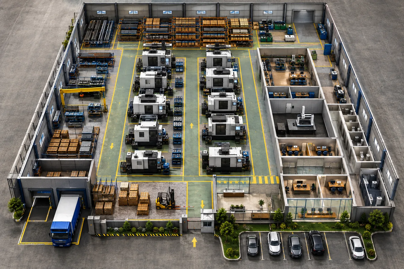
CNC Plant Space Requirement Calculation Guide
15 min read
What Is Industrial Architecture?
10 min read
Foundry Layout Planning Guide
14 min read
Plant Expansion Readiness Guide
11 min read
Plastic Recycling Plant Design Guide
12 min read
Factory Master Planning Decisions
13 min read
Plant Material Flow Planning Guide
12 min read
Hiring an Industrial Design Consultant
12 min read
Industrial Warehouse Planning
12 min read
Pharma Facility Planning & GMP
14 min read